Learning Assembly — Part 4.2
Let’s Write Some (Harder) Assembly Language Code!
Looking at how to do multiplication on the 6502, we can further explore how to write Assembly Language code
Writing Assembly Language (I believe) requires you to think about writing code in a different way. What I mean by this is that everything is very granular. What I mean by that is that you have extremely fine control over what is happening. This level of control is not available to us in most other languages. We recently looked at some small examples (addition and division) of how to write in this language. However, by only considering simple situations we are restricting ourselves to only knowing a small amount of the features of the language.
Here, we will look at a more complex example — multiplication. This is an exciting example, covering way more of the instruction set. It will also challenge us to consider how to perform a more difficult procedure where we will need to save multiple values and carry out loops.
Combined with Part 4.1, this is Part 4 of a “learning assembly” series I am writing. However, wherever possible I am trying to ensure each part is independent. If all you’re interested in is getting the basics of assembly, hopefully, these two posts will be suitable for you as well.
Multiplication
Multiplication is more difficult than addition. This is primarily because we don’t have a single instruction that can do it — we need to make our own way. This is a really good example to learn as it uses a nice variety of different instructions and techniques. We will start by looking at how we normally do multiplication and build from there.
   12
*̲ ̲ ̲2̲3̲
   36
+̲ ̲2̲4̲0̲
= 276
This (hopefully) looks familiar. This is how we can multiply normal, decimal numbers. Going forward, we will call the top number the multiplicand (MPD) and bottom the multiplier (MPR). Here then, 12 is our MPD and 23 our MPR. Let’s try to really break down exactly how we could have done this multiplication:
- Take the right-most digit from the multiplier (23), this is 3. Then, multiply this by 12. We now have 36
- Take the next digit from the multiplier (23), this is 2. Then, we shift the MPD (12) to the left, giving us 120. Now, multiply these together. This gives us 240.
- combining these gives us 276.
This is the correct result. Shifting the MPD to the left, then multiplying it with the appropriate digit from the multiplier will be an important way to consider multiplication in this example. To do this with binary numbers we do the same procedure:
    101 (MPD)
*̲ ̲ ̲ ̲0̲1̲1̲ (MPR)
    101
+  1010
+̲ ̲0̲0̲0̲0̲0̲
= 01111
In this example, we are doing 5 (101) multiplied by 3 (011). 101 is the multiplicand (MPD) and 011 is the multiplier (MPR)
- We take the first bit of the MPR (011). This is 1. We can call the bit we are using our significant bit. We multiply the MPD (101) by this. We are left with 101
- Then, we shift the MPD to the left, giving us 1010. The second bit of the MPR is also 1. We multiply these two together, and we are left with 1010.
- We shift the MPD left once more. This results in 10100. The final bit of the MPR is 0 which means this gives us 00000
- Adding them altogether leaves us with 01111, which is 15.
Again, we have the correct result. To recap, if the significant bit of the MPR (the multiplier) is 1, you keep the result. Then, regardless of that, shift the original thing (the multiplicand — MPD) to the left. You repeat this procedure until you are sure all the bits of your number have been inspected.
Flow Charts
This can be shown in a flow chart. This is useful to do before it comes to actually write the code as it can help you visualize the problem you are tackling. This is good as, compared to our nice high-level modern languages, it is harder to just go for it and write a function.
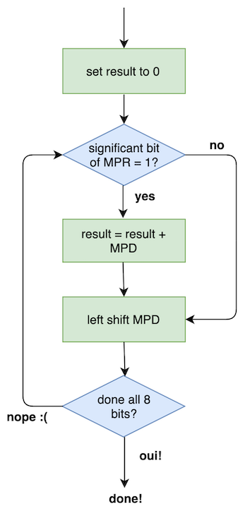
It might be confusing at first, but this figure shows the same logic we had to do to multiply the binary numbers above. It’s worth thinking about the chart and trying to understand it. It tripped me up until I considered that if the significant bit of MPR = 0, then it would never contribute to the result.
Our next step is to convert this into code. Lets quickly consider some problems/ edge cases we might face while doing this though:
- Multiplying two 8-bit numbers could result in 16-bit one. To get around this we will need to store the result in two 8-bit locations. One for the lower bits and one for the higher bits. For example, we can store 326 as two 8-bit numbers like
00000001and01000110and then read it all together like00000001 01000110. - We have to keep track of a lot of information to do this calculation. We will be forced to use more than just the registers (X, Y, A, etc) the 6502 has.
- There is no way to test and make a comparison on every bit of a number at once. To do this, we have to individually move the bits into the Accumulator (A) or the Carry register (C) and do our comparisons there.
The Code
I will just present the code and then we can go through it line by line:
START   LDA     #0       ; zero accumulator
        STA     TMP      ; clear address
        STA     RESULT   ; clear
        STA     RESULT+1 ; clear
        LDX     #8       ; x is a counter
MULT    LSR     MPR      ; shift mpr right - pushing a bit into C
        BCC     NOADD    ; test carry bit
        LDA     RESULT   ; load A with low part of result
        CLC
        ADC     MPD      ; add mpd to res
        STA     RESULT   ; save result
        LDA     RESULT+1 ; add rest off shifted mpd
        ADC     TMP
        STA     RESULT+1
NOADD   ASL     MPD      ; shift mpd left, ready for next "loop"
        ROL     TMP      ; save bit from mpd into temp
        DEX              ; decrement counter
        BNE     MULT     ; go again if counter 0
We have multiple named blocks of code now. Why is this useful? Well, we can make comparisons and jump to these blocks depending on the result. This is what BCC and BNE will do. If that contents of the Carry bit is 0, BCC will do a jump. The instruction BNE can cause a branch as well if the Z flag is equal to 0. Knowing this, we can go through our code, while trying to keep in mind the flow chart we drew.
START
This section is to set everything up for later. It is the equivalent of the top-most green box in the Flow Chart above. We want to ensure the memory locations we will be using have been cleared. Recall, we mentioned above of a problem where we ended up with a number that could not be held in 8-bits. Therefore we have not 1, but 2, places to store our results (RESULTand RESULT+1).
START   LDA     #0       ; zero accumulator
        STA     TMP      ; clear address
        STA     RESULT   ; clear
        STA     RESULT+1 ; clear
        LDX     #8       ; x is a counter
👉 Line 1: We load the Accumulator with 0, this will be used to set areas in memory blank.
👉 Line 2/ 3/ 4: Three locations in memory are set to be empty by transferring the contents of A into them. These locations include a temporary holding area for values (TMP) and two locations where we will store the result (one for the upper 8 bits of the result and one for the lower 8 bits).
👉 Line 5: The X register is loaded with the value 8. This will be used to count how many times we have shifted our values left. We can increment X downwards by using the instruction DEX.
MULT
Think back to the examples above of how we multiplied above. We checked if the significant bit of the multiplier was a 1, if it was we could add the multiplicand to the result. This part of the code handles one of those loops. It is the equivalent of the top-most blue diamond (and the green box below it) in the Flow Chart above.
As the program runs, we will visit this part 8 times, once for each bit in the multiplier.
We mentioned that there will be two areas for the result. We will use the contents of the carry register to, effectively, link these together. Therefore, if we work on the lower half we don’t need to worry about C, but when we work with the higher half of the result we will — we need to know if there’s anything to include.
MULT    LSR     MPR      ; shift mpr right
        BCC     NOADD    ; test carry bit
        LDA     RESULT   ; load a with low res
        CLC
        ADC     MPD      ; add mpd to res
        STA     RESULT   ; save result        LDA     RESULT+1 ; add rest off shifted mpd
        ADC     TMP
        STA     RESULT+1
👉 Line 1: LSR is one of the shifts we saw in the last part. This will cause the significant bit of our multiplier to fall into the carry register.
👉 Line 2: BCC test the contents of the carry. If it is 1 we will continue with the next line and we will try to include our calculation in our result. However, if it is 0 we will jump to the block of code we have titled "NOADD". This will ignore the rest of the MULT block.
👉 Line 3: Assuming the contents of the carry register is 1, we now put the current contents of the lower part of our result into the accumulator.
👉 Line 4: As there is no need to carry anything into the lower half of the result we can do a CLC , this clears the carry register. This won't be necessary when taking care of the top half of the bits though - we will want to know if something has carried from the lower to the higher part.
👉 Line 5: As the MPR is 1 we can include the MPD in the result. The current result of the calculation is in the Accumulator. The ADC here will add the current multiplicand (MPD) to the result as well.
Adding Result and MPD could result in a number bigger than 8-bits. This new 9th bit would fall into the Carry register, where we would need to add it into Result+1
👉 Line 6: We now save the lower result back to RESULT. As we go through the calculation the lower half of the result will accumulate here.
👉 Line 7/ 8/ 9: this does a similar thing as lines 3/ 5 and 6 but for the top bits. The memoryTMP will include information about the upper half (what cannot be stored in the first 8-bits) of the calculation, as we will soon see. Note, for this part we haven’t cleared the Carry, we need to know what happened in the lower half.
After these lines, we naturally begin the NOADD part.
NOADD
We naturally enter this block after every loop through MULT. However, if we are not going to add anything to the result in a specific loop we will be sent here as well. This part of the code will shift the multiplicand to the left. It will also prep TMP , which helps us keep track of the upper 8-bits of the calculation. Finally, here we will keep track of whether we have looped through every bit of out multiplier — if we have, then the multiplication will be complete. It is the equivalent of the bottom two boxes in the Flow Chart above.
NOADD   ASL     MPD      ; shift mpd left
        ROL     TMP      ; save bit from mpd
        DEX              ; decrement counter
        BNE     MULT     ; loop back to MULT
👉 Line 1: ASL shifts the multiplicand left. It is the "opposite" of LSR. This gets it ready for when we loop around. This pushes the left-most bit of MPD into the Carry register
👉 Line 2: After Line 1 something will fall into the Carry. This can be recovered into TMP by using the instruction ROL, which will push the contents of the carry register into TMP’s right-most bit. This is done so this bit can be included in the upper bits of the result (see MULT).
👉 Line 3: DEX reduces the X register by 1. X is keeping track of how many times we have looped through the code.
👉 Line 4: Here, we determine if we need to loop back to the beginning of MULT and continue our calculation. To do this we use the instruction BNE. BNE branches if the contents of the Z register equals 0. The Z register will automatically be set to 1 whenever DEX sets X to 0. So, if line three decreases X to 0, Z will be set to 1, and therefore we will not branch. The program will end. This will happen after all the bits in MPR have been used and therefore the calculation is finished.
If we were still in the middle of the calculation and reached this part, the multiplicand will have been shifted left, and we will be ready to loop back to the beginning. There, we would find the next significant bit of the multiplier and check if it needs to be added to the result.
Done! Doing this whole procedure will multiply 2 numbers. It is a little complicated, right? It does follow our flow chart though, which follows the logic of how we did the multiplication to begin with. It is a useful example, one worth trying to fully understand, as it contains a lot of important instructions and ideas.
Instruction Set
We have now seen a variety of the 6502 instruction set. However, there is still a lot more. These two examples do show us what sort of instructions are available. Broadly, they fit into the following categories:
- Data processing (ADC, DEX)
- Data transfer (LDA, STA, LDX)
- Shifts (ROL, LSR, ASL)
- Testing and Branching (BCC, BNE)
- Control (CLC, CLD)
Many more exist in each category. At this point, most resources will take time (usually around 100 pages) to discuss every instruction. This sort of reference material can be very useful and would provide an in-depth description of every aspect of the instructions. However, I am not going to do this here. Its a bit dull to write, and not super interesting to read. A lot of the instructions that we have not seen yet are variations of the ones we have (DEY decrements the Y register, SBC subtracts...). The best way to learn how they all work is to use them or see them used in examples. We will try to provide more examples here in the following weeks. Regardless, the books I mention at the bottom of the page (Zaks and Leventhal) are fantastic resources too.
Conclusions
This is a much more complex example than we saw previously, however, it does touch upon a lot of different features of the language. It took me ages to fully grasp what was happening at each stage of the code, but I think it is a useful (and fun!) example.
Next week, we will concentrate on trying to get this code to actually run. We will do this by installing an assembler and emulator. We will be able to get a sense of how developing software using 6502 Assembly Language happened.
This is the fourth-ish part of my “learning assembly” series.
- Part 1: Introduction to 6502 Assembly
- Part 2: Get to Grips with Binary Numbers
- Part 3: How do Processors work?
- Part 4.1: Let’s Write Some Assembly!
- Part 4.2: Let’s Write Some (Harder) Assembly!
- Part 5: The Apple ii
This article has been adapted from my personal blog. Most of the content I talk about will come from two main sources: “6502 Assembly Language Programming” by Lance A.Leventhal and “Programming the 6502” by Rodney Zaks.