Understanding TCP internals step by step for Software Engineers and System Designers — Part 1

When we hear of networking & related topics like connection, protocols, data transfer, the dreaded university lectures & boring slides come to our mind (probably to most of us). As software engineers, we can’t be fearful of technical details of networking, all of us may not be network engineers, still we need to know enough details so that we can make proper decision with minimum & appropriate trade-offs while designing a system architecture.
Most of the networking books or slides are fat, very serious, covers many topics in minute details. This post is designed exactly opposite to that, it explains few networking concepts & TCP in a top-down fashion from a software engineer’s perspective in simple English accompanied by enough technical details so that once you go through it, you get a clear picture of how, what & why of different aspects of TCP. I try to cover several important items on this topic in a systematic manner,.
This is the first part of the article series, it’s intended to build the base of this series. It starts from the high level understanding of networking concepts like data flow models & how data flows in the network stack, it later discusses in details about TCP connection life cycle, TCP header structure, what each field in a TCP header means etc. If you understand these basics, it would be easier for you to understand the advanced stuffs in the next articles.
This article can help any level of software engineers, network engineers, system designers / architects, university students & software engineering interview candidates (if appearing for system design & architecture interview) who want to brush up on the concepts of TCP.
Network Data Flow
Data Flow Models
Remember OSI(Open Systems Interconnection) & TCP/IP model reference? I shall explain the necessary details in short, knowledge of data flow is the prerequisite to understand deeper technical details further.
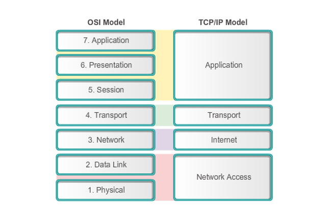
OSI is a conceptual, protocol independent model of network communication which can help you to understand how data flows across the network, what are the logical layers & how networking applications & devices communicate with each other. It has 7 layers:
Application Layer: This is the layer on which networking applications / programs operate & users interact. When you create a Facebook or Instagram story or do a mobile payment, all you do is just make few clicks on the screen or type in some data , you don’t really care about how the story is being shared or the payment has been made — this is what application layer is.
Presentation Layer: Whether you upload a video or image or type in a status in your local language, some layer has to convert the application data to network & operating system friendly data — that’s presentation layer. Actual information existing in the form of character strings, numbers, symbols is encoded into bit streams, converted into another form and compressed by this layer. Also what about encrypting your data to save it from hackers? The same layer does it, any sort of translations / conversion, encryption or compression of data happens in this layer.
Session Layer: When you are already logged in to Facebook, it would not feel right if the app suddenly logs out or the connection to the server terminates with sudden error message. Devices need constant communication especially in the current world when many apps are near realtime. The conceptual layer which handles such long running communication among devices is called Session layer. A session attaches the receiver to a particular server for some time. Dialog control, token management and synchronization of interaction between sender & receiver is done in this layer.
Transport Layer: When you upload a video status, it’s not like you just choose or record a video & it magically lands at the server side. When data communication happens, there are many variables & constraints involved (we will discuss later), someone has to decide how much data your device can send to the server at a certain point in time, how much it can receive from the other side, how to change the rate of sending when required, how to make a reliable & error free data transfer without causing much harm to the sender & receiver, how to reassemble data in particular order since data can be lost while being transferred — this is Transport layer. This layers orchestrates & abstracts out data transfer & delivery on top of layers below it but is not directly responsible for host to host data transfer.
Network Layer: Internet is not a big monolithic network, it consists of numerous smaller networks (called sub-nets) connected to each other, example: when you access internet from your home, you are possibly in your home network, your home network has a publicly visible IP address, all computers connected to the home network have same public IP address outside of the home network. If any other network wants to send data to your computer, they can send the data to your home network address, then the home network can distribute the data to the specific computer. This mechanism of converging multiple connected computers’ address to a single public address is called Network Address Translation (NAT). This network to network data transfer & NAT is done by the network layer. This layer extracts IP address from TCP/IP data units, performs host resolution, calculates optimum data flow path using specific algorithms. Routers operate in this layer, a router sits between two networks & acts as intermediate destination for network traffic. Routers may connect to modem given by Internet Service Provider (ISP). Modem is a gateway to the ISP internet network.
Data Link Layer: Inside a network, computers & devices need to connect to each other physically to be able to communicate. Devices plug into something called ‘Switch’, it’s a hardware which knows MAC address (physical address) of all devices connected to it. A switch may connect to a router. So a piece of data passes from device to switch to router to modem to the ISP network. This hop to hop data transfer is done by data link layer. This layer converts the data given by network layer into something called frames, & it reliably transfers frames from one hop to another. It does flow & access control of the frames.
Physical Layer: Computers in a network are connected by some means like — standard copper cable line, coaxial cable line, fibre optic line, satellite connection etc. These are the physical layers, where data actually gets transmitted. “The physical layer deals with the description of the characteristics of the interface between the devices and the transmission media, representation & synchronization of the bits, data rate, physical topology, line configuration, transmission mode”.
Here is an image representing what all layers in OSI do:

Following is a very simplified diagram to understand the communication & networking between device, switch, router & modem.
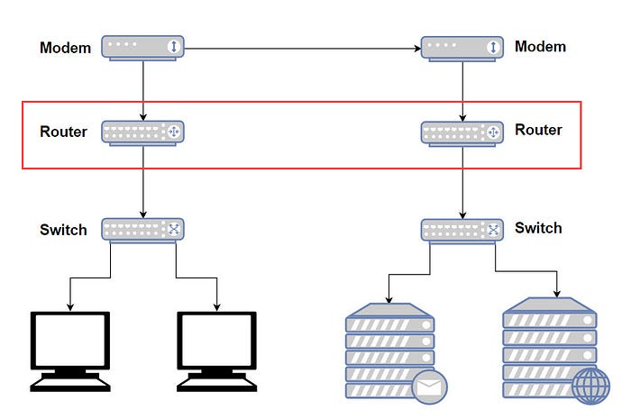
Here, as example, say in your office, there are 2 networks, one for personal devices (left side of the image), another one for servers (right side of the image). All personal devices are connected to a switch, servers are connected to another switch. Since the office wants to make 2 networks, each switch connects to different routers. Routers connect to different modem probably because the physical medium for the networks are different — personal network is connected to the ISP through standard copper cable connection, whereas server network is connected to the ISP through a high speed fibre connection. Modems are optimized for different physical mediums, hence for each type of physical connection, you may need a different type of modem.
The TCP/IP network model just amalgamated several layers of OSI into a single layer. While there are conceptual similarities between this model & OSI, some notable differences are — OSI model is protocol independent, whereas TCP/IP reference model has its own set of protocols in all of its layers (TCP/IP model refers to a suite of protocols). OSI model transport layer is connection oriented (requires prior connection set up before data transfer starts) & guarantees data delivery where as TCP/IP reference model transport layer is connection-less (doesn’t require prior connection set up before data transfer starts) & doesn’t guarantee data delivery still it’s usually reliable. OSI is conceptual as already stated whereas TCP/IP model is an implementable client server model.
We are interested to learn internals of TCP in this article series, so where does TCP fit in the above network model?
TCP is a transport layer protocol, it’s not the only protocol in this layer though, there are other protocols such as UDP. There are many formal definitions of TCP in the internet. Most of them define TCP as a connection oriented, highly reliable communication protocol which maintains a stream of data transfer between the sender & the receiver. A lot goes behind to make it happen, we will see shortly.
Note: Notice that we have used TCP here in two contexts — i. TCP/IP reference data model: It’s a suite of protocol as described above, not a particular protocol itself, ii. TCP protocol, a transport layer protocol. Don’t get confused between them.
When you make an API request, transfer a file, send a message, upload Instagram image, do anything over the internet that needs communication with external server(s), data transfer happens from your application to the remote receiver through multiple layers — first data passes through sender side networking stack (operating system level implementation of TCP/IP data model we just saw sometimes back), then through the external network of computers, then through the networking stack of the receiver.
Following is the high level data flow through TCP/IP stack:
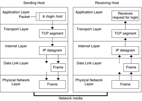
Any layer in the above image can transfer data to the layer just above or under it depending on whether the system is acting as a sender or a receiver.
Every layer has its own name to identify an unit of data. TCP (transport layer protocol) terms an unit of data as segment, UDP (transport layer protocol) calls unit of data as datagram, internet or IP layer calls it a datagram ( or sometimes as packet ), data-link layer & physical layer or network interface layer calls it a frame.
There are lot of confusion about naming, many documentation or articles use the word ‘packet’ very generously to describe TCP segment, IP datagrams & application level data units. Even TCP RFC documentations also confuse such terminologies. In the end of the day, whether it’s called packet or frame or segment, everything is just application data in some format or other appended to extra metadata at each layer, as described below.
With respect to the TCP/IP model reference, the transformation of data from the application layer to the network layer is shown below & explanation follows.
The data starts flowing from the application layer (OSI layer 5, 6, 7). All sorts of data conversion ex. from ASCII to EBCDIC, encryption etc happens in this layer. Application layer creates header with necessary information, talks to DNS (in windows networks, WINS — Windows Internet Name System ) to resolve the IP address of the receiver, packs that with destination port to create a socket address, puts the socket address in the header, attaches application data bytes after the header to create an unit of data. Data is sent to the transport layer as a stream of bytes since transferring large data to the kernel at once would be inefficient.
Transport layer protocol ex. TCP convert those bytes into segments. So some sort of further chunking or reassembling of data happens here. A TCP segment contains a TCP header & a chunk of data passed from the application layer. This process of converting data bytes to segments is called TCP Segmentation. TCP layer creates a virtual connection with the receiver, puts source and destination ports in the segment headers.
We discuss internals of TCP connections & TCP segment structure later in this article.
The transport layer protocols pass down the segments to the Internet layer (IP layer), where the IP protocol prepares them for delivery. IP can further fragment TCP segments (this is called fragmentation) & attaches IP header over the top to create an unit of data called IP datagram (sometimes called IP packet). If multiple fragments are created out of a transport layer segment, IP allocates an unique sequence number to each of them so that they can be assembled at the receiver side IP layer. IP is unreliable, does not guarantee data delivery. IP provides a great abstraction over the underlying network & can be used over a heterogenous network (i.e., a network connecting two computers can be any mix of Ethernet, ATM, FDDI, Wi-fi, Token ring, etc.) and it makes no difference to the upper layer protocols.
Broad technical discussion on IP is out of the scope this article.
IP datagrams are passed to the data link layer. The most important thing this layer does is converting IP address to MAC address (physical address). Address Resolution Protocol (ARP) is used for this conversion. This layer formats a datagram to a frame by attaching another header to it. The frame header includes a cyclic redundancy check (CRC) field that checks for errors as the frame travels over the network media. Protocols such as PPP can create direct network connection between routes. Data link layer then hands over the frame to the physical layer.
ARP is used predominantly to convert an IP address to a Ethernet MAC address, but it can actually be used to convert many other different network layer protocol addresses to hardware addresses. ARP is not just an IP-only or Ethernet-only protocol. In fact not only for IP over Ethernet, ARP can also be used for IP over other LAN technologies such as Token Ring, FDDI, or IEEE 802.11, ATM etc.
The physical network sends the frames out over the network media. It deals with physical characteristics of the medium, converts all frames to code & symbols that are converted to physical signals & transmitted to the network medium.
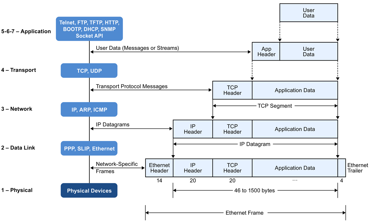
In brief, when data gets transferred through layers, each layer adds its own header, can remove or add some elements in the existing data, each layer may fragment data units to match the size of the downstream layer to reduce fragmentation. This process is called network data encapsulation.
TCP segment encapsulates application data, IP datagram encapsulates TCP segment, data link layer like ethernet encapsulates IP datagram into frames, physical layer converts those frames into physical medium friendly signal.
What about the size of data unit at each layer?
MTU & MSS: MTU or Maximum Transmission Unit is the maximum datagram size that a given data link layer supports.
MSS or Maximum Segment Size is the maximum TCP segment size. MSS actually refers to only TCP payload (data) size, it excludes TCP header size.
MSS = TCP payload or data size excluding TCP headerMTU is used for fragmentation i.e packet larger than MTU is fragmented. When upper layer passes data whose size is greater than supported MTU size, data link layer fragments that data. This is a costly process, typically we try to avoid fragmentation. So Upper layer needs to decide on data size which is usually less than MTU size. MTU size does not include link layer (ex: Ethernet) header size.
MSS is calculated from MTU with the following formula:
MTU = IP header (minimum size = 20 bytes) + TCP header (minimum size = 20 bytes) + TCP payload (or MSS)=> MSS = MTU - 40
In the 3-Way Handshake (described later in this article), during the SYN packet transmission, MSS value is decided between the sender & the receiver.
MTU size depends on the link layer, not all link supports the same size, some examples are given below:
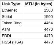
IP MTU: Same concept as MTU but for IP layer. It’s used to fragment data at the IP layer. Minimum size is 128 bytes; maximum depends on the interface medium.
IP MTU = IP header + TCP header + TCP payload (MSS)Changing the MTU value (with the mtu interface configuration command) can affect the IP MTU value. If the current IP MTU value is the same as the MTU value, and you change the MTU value, the IP MTU value will be modified automatically to match the new MTU. However, the reverse is not true; changing the IP MTU value has no effect on the value for the mtu command.
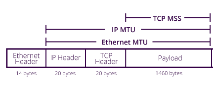
See the following figure for visualizing MTU, IP MTU & MSS, look at how headers are included or excluded while calculating MSS or MTU. The payload size 1460 bytes for MSS is just an example payload, you don’t need to bother about it.
Some details on MSS & MTU can be found here as well.
Some Data on Header & Payload size
HTTP maximum header size: HTTP specification does not talk about maximum allowed header size. Although web servers put their own limit. Apache limits max header size to 8 KB, Nginx has a limit of 4 KB to 8 KB, IIS limit is 8 KB to 16 KB, Tomcat limit is 8 KB to 48 KB.
HTTP maximum payload size: Again HTTP specification does not impose any limit on maximum allowed payload size, it depends on server configuration & the server size code logic if any.
TCP segment size: Minimum TCP header size is 20 bytes, maximum is 60 bytes. Theoretical limit on maximum possible TCP segment size (header + payload) is 65535 bytes although as described already MSS (only payload) is decided based on MTU size to avoid link layer fragmentation & packet loss.
TCP Segment Size = TCP header size + MSSIP datagram size: Minimum IP header size is 20 bytes, maximum is 60 bytes. Theoretical limit on maximum possible IP datagram size is 65535 bytes. Although practically this is not the size for the same reason as TCP.
Data link layer / Ethernet Frame size: Header size 18 bytes. Header includes source and destination MAC Address, the protocol type, followed by the frame check sequence placed at the end of the frame.
Minimum payload size at this layer is 46 bytes, maximum is 1500 bytes.
TCP Connection Stages
IP or Internet Protocol offers host to host routing & addressing. IP is unreliable. TCP is abstraction over IP providing re-transmission of data in case of lost data, ordering of data, congestion control & avoidance, data integrity & more, TCP stream is completely reliable. TCP is optimized for accuracy rather than timely delivery.
HTTP standard does not only specify TCP as the only transport protocol, rather we can use UDP or any other transport protocol. Since TCP is reliable & comes with great features, all HTTP traffic in practical are delivered via TCP.
TCP is connection oriented protocol, in order to transmit segments from the sender to the receiver, a TCP connection needs to be established between them. TCP connections go through a complete life cycle, roughly, the stages of a TCP connection are — establish connection, transfer data, terminate connection.
Let’s briefly looks at the broad picture of how a TCP connection is established between a sender & a receiver. This will help us to understand the full TCP connection life cycle later.
Three-Way Handshake:
Before application data starts transferring between client & server, TCP connection has to be established — both sides need to agree on packet sequencing & number of TCP connection variables. This is how it starts:
SYN — Client picks a random sequence number & sends a SYN packet with other TCP flags & options.
SYN ACK — Server increments x by 1, generates own random sequence number y, appends its own set of flags & options & dispatches the response.
ACK — Client increases both x & y by 1 & dispatches the last ACK response to complete the handshake.
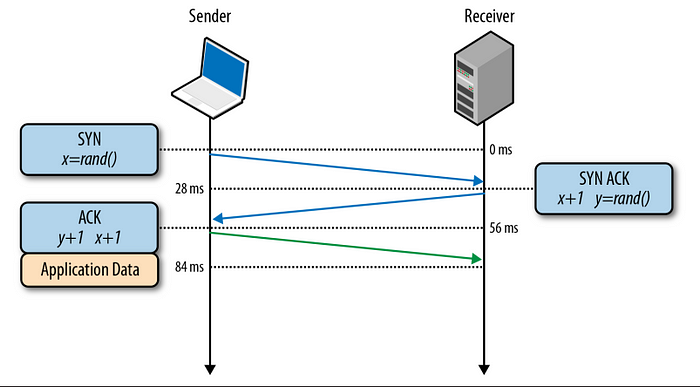
Client immediately starts sending data packets after sending the ACK packet, but the server must wait for the arrival of ACK. So SYN -> SYN_ACK takes a full round trip time in the network, also ACK adds more time to that. This delay of establishing connection through 3-way handshake is very significant & introduces latency in the client server communication. This latency is due to the propagation time between client & server, not due to bandwidth of any side. Hence managing a persistent TCP connection / reusing connection has lot of importance rather than just opening a new connection every time.
TCP Fast Open
The TCP handshake phase has been identified as a significant source of total web browsing latency, in large part due to the prevalence of very short TCP flows required to retrieve dozens to hundreds of assets from various hosts.
TCP Fast Open (TFO) is a mechanism that aims to reduce the latency penalty imposed on new TCP connections. Based on traffic analysis and network emulation done at Google, researchers have shown that TFO, which allows data transfer within the SYN packet, could decrease HTTP transaction network latency by 15%, whole-page load times by over 10% on average, and in some cases by up to 40% in high-latency scenarios.
Both client and server TFO support is now available in Linux 3.7+ kernels, which makes it a viable option for new clients and servers. Having said that, TFO is also not a solution to every problem. While it may help eliminate the round trip penalty of the three-way handshake, it also works only in certain cases: there are limits on the maximum size of the data payload within the SYN packet, only certain types of HTTP requests can be sent, and it works only for repeat connections due to a requirement for a cryptographic cookie. For a detailed discussion on the capabilities and limitations of TFO, check the
latest IETF draft of “TCP Fast Open.”
The Complete TCP Connection Lifecycle
Let’s understand what life cycle states does a TCP connection goes through both at the receiver & the sender side.
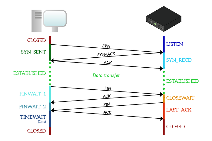
CLOSED: This state can be thought of as starting state as well as end state for a TCP connection. Since the connection is not established yet, the initial connection is simply considered to be closed.
LISTEN (Sender side state): The sender is always listening is to new connection requests. Once it receives a connection request, that connection will move ahead with further states as below.
SYN_SENT (Receiver side state): Receiver sends a SYN segment to server to start the 3-Way handshake process & moves to SYN_SENT state.
SYN_RECD (Sender side state): The sender receives (assuming no data loss) the SYN segment, sends a SYN_ACK (SYN+ACK) segment to the receiver indicating that it has received the connection handshake request from the receiver. The server side TCP state is now SYN_RECD
The client is still in SYN_SENT state, it receives (SYN_ACK / SYN+ACK) segment from the server, sends back ACK indicating the completion of 3-Way handshake. The server is still in SYN_RECD state.
“Three-Way Handshake” section already describes this mechanism in details.
Now the connection is established & both side is ready to exchange data.
After data is exchanged, any side can ask for connection termination. Let’s say for our case, the receiver asks for connection termination, we call it the initiator & the opposite side as responder.
Terminating TCP connection is not a straight forward process, it’s a 4-Way Handshake process.
FIN_WAIT_1 & CLOSE_WAIT: The initiator will send a FIN to the responder, it moves from ESTABLISHED to FIN_WAIT_1 state, and the responder will move to CLOSE_WAIT state as soon as it receives that FIN, sending an ACK in response.
FIN_WAIT_2: When the initiator receives that ACK, it will just move to the FIN_WAIT_2 state and will sit there doing nothing. The responder is still in the CLOSE_WAIT state, as it is waiting for the application to finish all its stuff and close.
LAST_ACK: As soon as the application at the responder side finishes, the responder will send a FIN to the initiator to tell that it also wants to close the connection, thus it transitions to the LAST_ACK state.
TIME_WAIT: Once the initiator receives the FIN from the responder, it will send an ACK and move to the TIME_WAIT state.
CLOSED: As soon as the responder receives the ACK, it will move back to the CLOSED state. After a timer of two milliseconds, the initiator will move to the CLOSED state too. The connection has now ended according to both parties involved.
Simultaneous Closure:
For a TCP connection to terminate, it is not necessary for a side to start the termination procedure & other end will follow up with that. Both the sides can start termination procedure together. Below diagram shows the process:
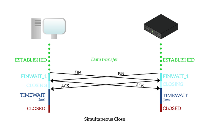
As you can see from the picture, this closure process is perfectly symmetrical. The client sends a FIN to the server to close the connection and moves to the
FIN_WAIT_1state. At the same time, the server sends a FIN to the client with the same intention, moving to theFIN_WAIT_1state too. The client receives a FIN, so it moves to theCLOSINGstate sending an ACK. The same goes to the server, which receives a FIN too and move to theCLOSINGstate by sending an ACK. When any of the two devices receives the ACK, it moves to theTIME_WAITstate and, after the timeout, to theCLOSEDstate. Basically, with a simultaneous closure, a FIN flag is received while still being in theFIN_WAIT_1state. — https://www.ictshore.com/
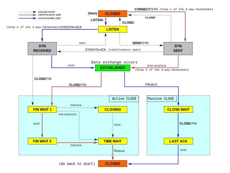
The state transitions along with associated actions are shown in the figure below, almost all the stuffs portrayed in the diagram is explained above:
Till now we have seen, how data flows in the network using TCP protocol, how connection is established & how are the connection states managed at the operating system side. But we have not yet seen what exactly gets transferred in the network. Since the article covers TCP, let’s see how a TCP segment looks like.
TCP Header Structure
It’s very important to know the structure of a TCP segment & what information it carries. The following shows the TCP header schema. A good part of the following explanation is taken from Wikipedia since it explains the structure quite well.
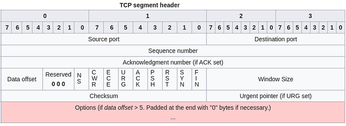
Source port: 16 bits — Identifies the sending port address (it’s not the sender IP address). If any interactive communication is happening between the sender & the receiver, the port helps the receiver to identify which port in the other side to send back the response to. If the receiver needs to send some response, the receiver will put sender’s port no as destination port in the TCP header of the response.
Destination port: 16 bits — Identifies the receiving port. Sender puts a destination port in TCP header signifying the port address in the receiver side where this TCP segment should land to, otherwise when the receiver receives the data, it won’t know to which port / process the data should be delivered.
Why TCP header only contain port address not IP address?
IP datagram header contains source & destination IP address since it’s in the network layer. As discussed earlier, an IP datagram encapsulates a TCP segment. TCP is in the transport layer, it does not care about IP addresses by design, it just needs to know the port address in the other side where the data has to be delivered. Neither of IP or TCP layer can determine the source & destination IP & port addresses. Application layer supplies these data points to the the underlying transport & network layer. These layers just picks up the appropriate data.
Sequence number: 32 bits — Has a dual role:
- If the SYN flag is set (
1), then this is the initial sequence number. The sequence number of the actual first data byte and the acknowledged number in the correspondingACKare then this sequence number plus 1. - If the SYN flag is clear (
0), then this is the accumulated sequence number of the first data byte of this segment for the current session.
Acknowledgement number: 32 bits — If the ACK flag is set then the value of this field is the next sequence number that the sender of the ACK is expecting. This acknowledges receipt of all prior bytes (if any). The first ACK sent by each end acknowledges the other end’s initial sequence number itself, but no data.
Data offset: 4 bits — Specifies the size of the TCP header in 32-bit words. The minimum size header is 5 words and the maximum is 15 words thus giving the minimum size of 20 bytes and maximum of 60 bytes, allowing for up to 40 bytes of options in the header. This field gets its name from the fact that it is also the offset from the start of the TCP segment to the actual data.
Reserved: 3 bits — For future use and should be set to zero.
Flags: 9 bits — (also called Control bits) Contains 9 1-bit flags:
- ACK — “Acknowledgment” flag which is used to acknowledge the successful receipt of a segment.
- NS (experimental flag) — Nonce Sum flag, used to help protect against accidental malicious concealment of segments from the sender. More details: RFC 3540
- ECE — This flag is responsible for indicating if the TCP peer is ECN (Explicit Congestion Notification) capable. See RFC 3168 for more details.
- CWR — “Congestion Window Reduced”, is used by the sending host to indicate it received a segment with the ECE flag set. More details: RFC 3168
- URG — The URG flag is used to notify the receiver to process the urgent segments before processing all other segments. The receiver will be notified when all known urgent data has been received. More details: RFC 6093.
- PSH — “Push” flag, like URG flag it also tells the receiver to process segments as they are received instead of buffering them.
- RST — “Reset” flag. When a host receives an unexpected TCP segment, that host usually responds by sending a reset packet back on the same connection. A reset packet is simply one with no payload and with the RST bit set in the TCP header flags.
- FIN — “Finished”, it means there is no more data from the sender. Therefore, it is used in the last segment sent from the sender.
Window size: 16 bits — The size of the receive window, which specifies the number of window size units (by default, bytes) that the sender of this segment is currently willing to receive.
Checksum: The 16-bit checksum field is used for error-checking of the header, the Payload and a Pseudo-Header. The Pseudo-Header consists of the Source IP Address, the Destination IP Address, the protocol number for the TCP-Protocol and the length of the TCP-Headers including Payload (in Bytes).
Urgent pointer: 16 bits — if the URG flag is set, then this 16-bit field is an offset from the sequence number indicating the last urgent data byte.
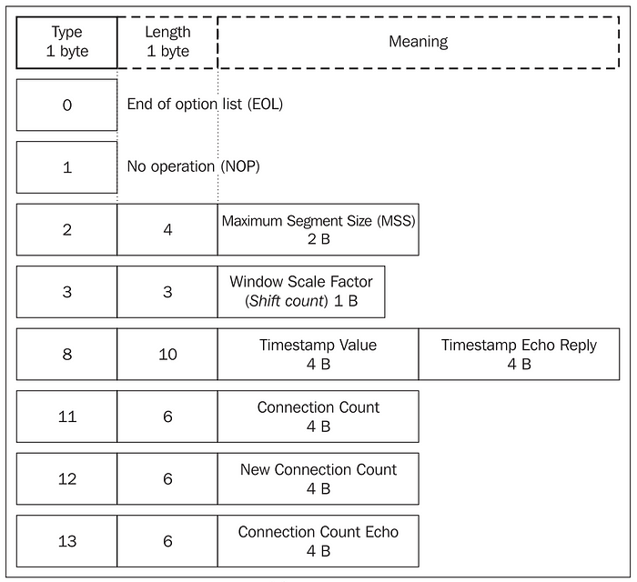
Options: Mandatory TCP header items take up 20 bytes. These mandatory items are followed by optional items. An optional item is made up of the optional item type, optional item length, and value. The length of the TCP segment must be a multiple of four. If the header length is not a multiple of four, it is padded with NOP (no operation) options.
Since the header length field of the whole TCP segment is only four bits long, this field can only contain a maximum value of 1111 (binary) =15 (decimal). The header length is determined in multiples of four, so the header can have a maximum length of 15 x 4=60 bytes. Mandatory items take up 20 bytes, so at the most only 40 bytes are left for optional items.
The following diagram shows some TCP header options and their structure. Many TCP options appear only during the initial SYN and SYN/ACK phase of the 3-way-handshake. Other options, however, can be used at will, during the TCP session.Some interesting items are the Maximum Segment Size (MSS) option, Window Scaling, Selective Acknowledgements (SACK). We have already discussed what MSS means, we will discuss others in the next article of this series.
An Important Stuff to understand: How does a receiver acknowledge received tcp segment?
We have just seen that a TCP header contains 32 bits acknowledgement number & a special 1 bit ACK flag. Say the sender sends a segment with sequence number 1000 to the receiver, the receiver receives it & it now wants to acknowledge the receipt of the segment. There are ideally two ways to do it:
- The receiver knows how many bytes it has receives, say it has received
200bytes of data, so the receiver has processed data till (1000 + 200) =1200offset already. In the acknowledgement, the receiver will send1200 + 1 = 1201(offset of next data) as the acknowledgement number & set theACKflag indicating the segment represents acknowledgement. So in the next transfer, the sender will transmit data bytes from offset1201. - OR another way is, the receiver does not care about the amount of bytes received, rather it just increments the server sent sequence number by
1, sets this incremented value (in the above example —1001) as acknowledgement sequence number in the TCP header along withACKflag being set. When the sender receives theACK, it knows that the receiver has received the previous segment completely & sends the next data bytes from offsets as requested.
It’s not necessary for the ACK segment to contain any data. If it does not have any data at all, it’s called pure acknowledgement.
In the next article of this series, we will discuss advanced stuffs that happen behind the scene to make TCP what it is.
Stay Tuned!
References:
- HPBN: High Performance Browser Networking.
- https://docs.oracle.com/cd/E18752_01/html/816-4554/ipov-29.html
- https://www.pcmag.com/encyclopedia/term/52615/tcp-ip-abc-s
- https://community.cisco.com/t5/vpn-and-anyconnect/difference-between-interface-mtu-and-ip-mtu/td-p/650311
- https://stackoverflow.com/questions/686217/maximum-on-http-header-values
- http://networkqna.com/what-is-the-difference-between-the-mss-and-mtu/
- https://www.custompcreview.com/articles/difference-between-modem-router-switch/
- https://www.quora.com/Why-is-a-router-connected-to-the-switch
- https://techdifferences.com/difference-between-tcp-ip-and-osi-model.html
- https://www.keycdn.com/support/tcp-flags

