Understanding TCP internals step by step for Software Engineers & System Designers — Part 2

In the first part of this series, we have seen networking & TCP basics which are necessary to understand the advanced stuffs discussed in this article. We saw what a TCP segment is, how it gets transferred through different network layers & how devices communicate with each other to transfer network data. We will now discuss what happens on the way when a segment is getting transferred, what kind of challenges are there, what kind of optimizations TCP apply for fast transmission & error control, what kind of optimization we developers can apply while developing applications.
Data Transmission Challenge: Network Congestion
Not all nodes connected to the internet have same link bandwidth. Hence the rate at which server sends data through the network may quickly overflow the buffer of intermediate nodes causing delay in round trip time of a segment & segment drop / unreliability in the network. Hosts may send the same packet several times to the receiver eventually some copy of each packets arrives at the destination. This is called Congestion collapse.
To address these issues, multiple mechanisms were implemented in TCP to regulate the rate with which the data can be sent in both directions: flow control, congestion control, and congestion avoidance.
Flow Control
It’s a mechanism to prevent the sender from overwhelming the receiver. Both receiver & sender broadcasts their receive window size (rwnd) which communicates the size of the available buffer space to hold the incoming data. During TCP connection 3-Way handshake, both sides initialize their rwnd size with system default settings. If a side is not able to keep up with the load, it can advertise a smaller window size. If window size is zero, it means no more data to be sent to the receiver until the application clears the buffer at the receiver side. This workflow continues throughout the lifetime of every TCP connection: each ACK carries the latest rwnd value for each side, allowing both sides to dynamically adjust the data flow rate to the capacity and processing speed of the sender and receiver.

Original TCP specification allowed 16 bits = 2¹⁶ ( 64 KB ) as the maximum allowable size for rwnd, but for some high bandwidth applications, the limit imposed limitation on the bandwidth. So RFC 1323 was drafted to enable TCP window scaling option which allows maximum rwnd window size to scale from 2¹⁶ to 1 gigabyte. The windows scaling option in communicated during 3-Way handshake process and carries a value that represents the number of bits to left-shift the 16-bit window size field in future ACK. Most major platform now supports window scaling. On Linux platforms, the window scaling setting can be checked and enabled via the following commands:
$> sysctl net.ipv4.tcp_window_scaling
$> sysctl -w net.ipv4.tcp_window_scaling=1
Is Flow Control enough to smoothly operate TCP on the network without much data loss? Seems like the answer is ‘No’. Consider the following simplified illustrative image which shows the bandwidth across different nodes in a network.
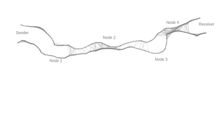
Here both sender & receiver operate with high bandwidth, node 2 & 4 have the least bandwidth, node 1 & 3 have relatively better bandwidth than node 2 & 4 but probably lesser than sender’s bandwidth. If a network request flows through the above path, sender & receiver behaves according to the Flow Control mechanism, it’s quite possible that node 2 will start dropping packets since it can’t handle high bandwidth as expected by the receiver. This is a big problem with TCP Flow Control mechanism that it cares about the sender & the receiver, but not about the underlying network. If due to bandwidth, the underlying network nodes like nodes 2 or 4 start to drop packets, there is no way that Flow Control can decide what the optimum quantity of packets that should be transferred without much loss.
This is where another mechanism called Congestion Control comes into play. It’s a mechanism which helps the sender to refrain from overwhelming the intermediate network nodes.
Note: Flow control takes care of not congesting only the receiver, whereas congestion control does the same for the whole underlying network.
Slow Start is part of congestion control which helps in regulating network traffic by negotiating amount of data that can be sent from the sender to the receiver.
Slow-Start
The only way to estimate the available capacity between the sender & the receiver is by exchanging data. Slow-Start mechanism does exactly the same. We have seen when a 3-way handshake is established, the receiver broadcasts its receiving window (rwnd) size to the sender in the ACK packet against SYN-ACK. In slow start, the sender refuses to send that much of data together initially. Rather the sender privately maintains something called Congestion Window per network connection at its end which the receiver is unaware of. Sender initializes congestion window size or cwnd variable to a very conservative value like 1 MSS. In TCP, at a certain point in time, the sender can send min(rwnd, cwnd) bytes of data to the receiver without receiving an ACK from the receiver, this data is called In-flight data (not ACKed data). In TCP it’s not like the sender sends a segment, waits for the ACK, once ACK is received then send another segment & continue, it’s not that sequential in nature. Rather for optimization purpose, the sender can send all In-flight segments together since the receiver is able to receive all of them together & then according to whether an ACK is received for a segment or not, further actions continue.
Slow-Start works as below:
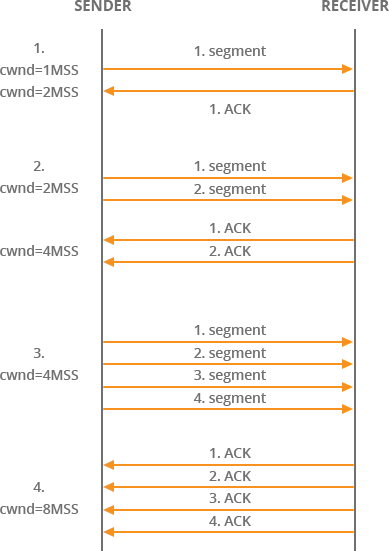
cwndis set to1 MSSinitially. The sender sends only1TCP segment to the receiver. A segment might contain some bytes or a kilobyte of data. RFC 2581 updatedcwndto a maximum of4 MSSin April 1999, and most recently the value was increased once more to10 MSSby RFC 6928 in April 2013. After sending in-flight data to the receiver, the sender must always stop & wait for acknowledgement.- The receiver receives the segment, sends an
ACKalong with its current receiver window sizerwnd. - The sender receives an
ACKfrom receiver. Sending a segment & receivingACKsuccessfully for that back at the sender takes one Round Trip across the network. Every round trip can accommodate sending & receiving not only one but multiple segments up to certain limit. After everyACKreceived, the sender increases thecwndsize by1MSS. Nowcwnd = 2 MSS. - The sender now sends
2segments to the receiver. - Receiver acknowledges the segments & sends an
ACKfor each of the received segments. So receiver actually sends2ACKone after another when it receives & processes those2segments. - Now the sender doubles the
cwndsize to4 MSS. - And as you see, the sender actually doubles the value of
cwndafter every successful network round trip. This phase in TCP connection is called exponential growth as both sender & receiver try to converge on available bandwidth on the network path between them.
Is there any end to the exponential growth of congestion window?
The transmission rate will be increased by the slow-start algorithm until either a loss is detected, or the receiver’s advertised window (
rwnd) is the limiting factor, orssthreshis reached. — Wikipedia
TCP uses a threshold limit called ssthresh which is initialized to a very high value (historically 65536). If cwnd size reaches this limit, congestion avoidance mechanism kicks in. In congestion avoidance, the cwnd size grows linearly as long as non-duplicate ACKs are received thus the throughput of the connection is capped.
Now a days, modern TCP implementation sets ssthresh to very high value like 2³¹. So cwnd size grows till either it reaches this size or some packet loss occurs indicating congestion on the way or duplicate ACK is received..
In some implementations (e.g., Linux), the initial
ssthreshis large, and so the first slow start usually ends after a loss. However,ssthreshis updated at the end of each slow start, and will often affect subsequent slow starts triggered by timeouts — Wikipedia.
In short:
if cwnd <= ssthresh, do slow start
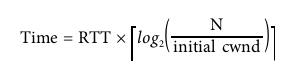
if cwnd > ssthresh, do congestion avoidanceThe following equation can be used to determine time to reach cwnd size of N using Slow-Start mechanism:
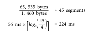
Example:
- Receiver and sender receive window size (N): 65,535 bytes (64 KB)
- Initial congestion window: 4 segments (RFC 2581)
- Say Round trip time: 56 ms.
- Say 1 segment = 1460 bytes.
Despite the 64 KB receive window size, the throughput of a new TCP connection is initially limited by the size of the congestion window. In fact, to reach the 64 KB limit, we will need to grow the congestion window size to 45 segments, which will take 224 milliseconds, that’s 4 round trips:
So, even if the sender & the receiver works in high bandwidth, it has no impact on Slow-Start mechanism, the process always starts with limited segment size.
Is Slow-Start good for all sort of network connections?
For large amount of data transfer, video streaming type applications, slow start is all fine because the sender & the receiver takes some hundreds of milliseconds time to arrive at the maximum receiving window size, after that period of time, data transfer is at maximum speed. So over long term for large data transfer, slow start time is balanced.
But for usual short lived HTTP connections, the connection itself may terminate even before the maximum window size is achieved. As a
result, the performance of many web applications is often limited by the round-trip time between sender and receiver: slow-start limits the available bandwidth throughput, which has an adverse effect on the performance of small transfers.
What are some optimizations to reduce the impact of Slow-Start in a TCP connection?
- Locate sender & receiver geographically close to each other. This will minimize the round trip time & hence can reduce total time required to achieve maximum window size.
- Check if the initial window size can be increased to
4or10segments. - Once a TCP connection is established between a sender & a receiver, try to keep that connection alive, so that in further communication between the same sender & receiver, the already achieved maximum window size can be used.
Slow-Start Restart
In addition to regulating the transmission rate of new connections, TCP also implements a slow-start restart (SSR) mechanism, which resets the congestion window of a connection after it has been idle for a defined period of time. The rationale is simple: the network conditions may have changed while the connection has been idle, and to avoid congestion, the window is reset to a “safe” default. Not surprisingly, SSR can have a significant impact on performance of long-lived TCP connections that may idle for bursts of time — e.g., HTTP keep-alive connections. As a result, it is recommended to disable SSR on the server. — HPBNOn Linux platforms, the SSR setting can be checked and disabled via the following commands:
$> sysctl net.ipv4.tcp_slow_start_after_idle
$> sysctl -w net.ipv4.tcp_slow_start_after_idle=0
As already described, slow-start starts conservatively, increases congestion window size by 1 on receiving every ACK ( or doubles the size after every successful round trip ). In this mechanism, a time may come, when the receiver process experiences less bandwidth on the connection — probably the receiver has to allocate some bandwidth for another process or the receiver process is somehow unable to process all the segments, so receiver slows down to respond to the sender. The receiver process may quickly become unable to accept more segments. This may introduce some congestion in the network.
Congestion Avoidance
TCP works on a fundamental assumption that once a packet is lost, it’s due to some congestion somewhere in the network, so there is a traffic jam in the network, TCP uses packet loss as a feedback to take corrective steps to slow down the congestion. Congestion window size has to be reduced so that the server does not keep sending same amount of data to the client. Once reduced, congestion avoidance algorithms start dictating how to increase or adjust the size further.
How do congestion control algorithms work?
Originally, TCP used the Additive Increase and Multiplicative Decrease(AIMD) algorithm: when packet loss occurs, halve the congestion window size, and then slowly increase the window by a fixed amount per round trip. However, in many cases AIMD is too conservative, and hence new algorithms were developed.
Proportional Rate Reduction (PRR) is a new algorithm specified by RFC 6937, whose goal is to improve the speed of recovery when a packet is lost. How much better is it? According to measurements done at Google, where the new algorithm was developed, it provides a 3–10% reduction in average latency for connections with packet loss.
PRR is now the default congestion-avoidance algorithm in Linux 3.2+ kernels. — HPBN
Fast Retransmit
Congestion can cause a TCP segment to drop in the network. A TCP sender typically keeps track of a sent segment by using a timer. If ACK for the sent packet does not arrive at the sender side till the timer times out, there is a packet loss. In Fast Retransmit, a sender does not wait for time out before retransmitting a lost segment.
If the sender has already sent say segments 1, 2, 3, 4, 5, 6, 7, 8 to the receiver, but the receiver only successfully received 1, say 2 & 3 were lost, so when segments 4, 5, 6, 7, 8 land at the receiver side, the receiver receives them but asks for the segment 2 in ACK since it lost segment 2 earlier. When the server receives such duplicate acknowledgement (typically 3 duplicate ACK long with one original ACK — in this case when segment 1 is received, ACK is done asking for next segment2(this is the first & original ACK confirming receipt of 1 and asking for 2), again for segments 4, 5, 6 as well, ACK was done confirming their receipt but asking for 2, since 2 is still not received at the receiver side — so one original ACK & three duplicate ACK for the same, in total four ACK has been sent for the segment 2), the sender identifies that segment 2 is dropped. So without waiting for timeout to happen for segment 2 (if not timed out yet), TCP retransmits the segment 2 again. This is called Fast Retransmit. In this mechanism, time is not lost waiting for a timeout in order for retransmission to begin.
But, why waiting for three duplicate ACK instead of one or two?
Since TCP does not know whether a duplicate ACK is caused by a lost segment or just a reordering of segments, it waits for a small number of duplicate ACKs to be received. It is assumed that if there is just a reordering of the segments, there will be only one or two duplicate ACKs before the reordered segment is processed, which will then generate a new ACK. If three or more duplicate ACKs are received in a row, it is a strong indication that a segment has been lost. TCP then performs a retransmission of what appears to be the missing segment, without waiting for a retransmission timer to expire. — RFC 2001
Fast Recovery
RFC 2001 describes this mechanism really well, following is the excerpt.
After fast retransmit sends what appears to be the missing segment, congestion avoidance, but not slow start is performed. This is the fast recovery algorithm. It is an improvement that allows high throughput under moderate congestion, especially for large windows. The reason for not performing slow start in this case is that the receipt of the duplicate ACKs tells TCP more than just a packet has been lost. Since the receiver can only generate the duplicate ACK when another segment is received, that segment has left the network and is in the receiver’s buffer. That is, there is still data flowing between the two ends, and TCP does not want to reduce the flow abruptly by going into slow start. The fast retransmit and fast recovery algorithms are usually implemented together as follows:
- When the third duplicate
ACKin a row is received, setssthreshto one-half the current congestion window size, but no less than two segments. Retransmit the missing segment. Setcwndtossthreshplus 3 times the segment size. This inflates the congestion window by the number of segments that have left the network and which the other end has cached. - Each time another duplicate
ACKarrives, incrementcwndby the segment size. This inflates the congestion window for the additional segment that has left the network. Transmit a packet, if allowed by the new value ofcwnd. - When the next
ACKarrives that acknowledges new data, setcwndtossthresh(the value set in step 1). ThisACKshould be the acknowledgment of the retransmission from step 1, one round-trip time after the retransmission. Additionally, thisACKshould acknowledge all the intermediate segments sent between the lost packet and the receipt of the first duplicateACK. This step is congestion avoidance, since TCP is down to one-half the rate it was at when the packet was lost.
There are some popular congestion control algorithm like TCP Tahoe & Reno which use Fast Retransmit & Recovery to control congestion. More details can be found here.
Bandwidth Delay Product
We know that maximum amount of in-flight data is minimum of sender side congestion window size (cwnd) and receiver side window size (rwnd). If the receiver gets bloated with packets & not able to process them somehow, it starts dropping packets & the sender does not get acknowledgement for those dropped packets. If maximum amount of unacknowledged packets is exceeded, the sender must stop sending new packets & wait for the receiver to ACK few packets. But how much time to wait?
That time is decided based on the round trip trip between the sender & the receiver. Congestion control & avoidance algorithms also suggest that the optimal sender & receiver window size must vary based on round trip time & target data rate between them.
Bandwidth-delay product (BDP)
Product of data link’s capacity and its end-to-end delay. The result is the maximum amount of unacknowledged data that can be in flight at any point in time.
When sender stops sending packet to the receiver frequently, a significant gap might be created where no data travels between them. So with zero data transfer rate during that time, maximum throughput of the connection is impacted. When receiver is busy processing data & generating ACK at its side, it does not mean it can’t process new requests, it means instead of sending large amount of data, if very less or just big enough data so that the sender & the receiver can keep communicating is sent, the receiver might accept those packets. When ACK of previous packets arrive at the sender side, sender can decide optimal congestion window size based on parameters like round trip time etc. Pick a low window size, and you will limit your connection throughput, regardless of the available or advertised bandwidth between the peers. The goal is to churn out the maximum throughput of the connection even if latency is there.
Head Of Line Blocking
Recall that TCP guarantees in-order delivery of packets from sender to receiver. To achieve that, TCP maintains unique sequence number in each packet header. Since network is unreliable, it might happen that receiver could not receive one or multiple packets. Consider the following diagram:
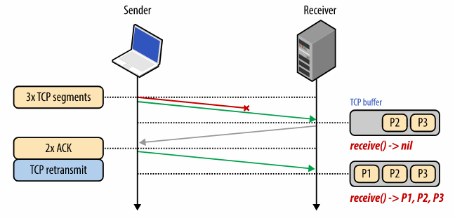
The sender here sends 3 TCP packets to the receiver — P1, P2, P3. But somehow P1 is lost, receiver only receives P2, P3 & does ACK for these 2 packets. When the sender does not receive ACK for P1, it re-transmits P1 & this time receiver receives it. Till the time P1 is not received at the receiver side, subsequent packets stay in the receiver TCP buffer. Until all packets in the sequence are strictly received, the receiver can not flush the data the application layer. This phenomena is called Head-Of-Line-Blocking, this is what creates the abstraction of in-order delivery for TCP. Applications at the receiver side don’t need to care whether packets arrive in proper sequence to make a meaningful message or not, it’s the responsibility of TCP, thus making application code lot simpler.
Any performance implication of TCP in-order delivery?
Latency. Since TCP performs reordering & reassembly of packets when a packet in-flight is lost, it creates unpredictable delay in packet arrival time commonly known as jitter. Applications may experience delay in this process.
Does all applications need reliable packet delivery?
No. Consider video streaming applications, music or podcast applications, online gaming, what matters in these apps is delivery & interpretation of current data packet, if any previous data packet is lost, that’s okay, probably few codecs will missed introducing a slight gap in the video or audio, the user might not even notice the gap if it’s very small, in the end what matters is — the application should broadcast live data at low latency.
Core Principles of TCP
Irrespective of underlying network or congestion control & avoidance algorithms used, the following principles hold true always.
- TCP 3-Way handshake introduces a full round trip of delay.
- TCP slow start is applied to every new connection.
- TCP flow & congestion control regulates throughput of all connections.
- TCP throughput is regulated by current congestion window size.
So the speed at which data can be transferred in modern high speed network is often limited by the round trip time between the receiver & the sender. Even if the bandwidth increases, still round trip time dominates impacting TCP performance as the biggest bottleneck.
Optimizing TCP performance
TCP is an adaptive protocol designed to be fair to all network peers and to make the most efficient use of the underlying network. Thus, the best way to optimize TCP is to tune how TCP senses the current network conditions and adapts its behaviour based on the type and the requirements of the layers below and above it: wireless networks may need different congestion algorithms, and some applications may need custom quality of service (QoS) semantics to deliver the best experience.
Tuning TCP optimization & algorithms is a big area of academic & commercial research. But as engineers, we can take some actions to get the best possible outcome.
Server (both sender & receiver) Side Optimization
- If possible, update the platform to use latest operating system kernel, kernels ship with latest updates of TCP & other stuffs. Updating kernel has its own risk & many system administrators might not do it probably because their existing kernel is set up with many configurations & their systems are closely knit with the existing kernel.
- Increase initial TCP congestion window size ( to
10) which allows more packets to travel in one round trip & help increase the window size to grow with better growth. This is a critical optimization for short lived & bursty connections. - Disable slow-start restart after idle which will help improving connections of long-lived TCP connections.
- Enabling window scaling increases the maximum receive window size and allows high-latency connections to achieve better throughput.
- TCP Fast-Open: Allows application data to be sent in the initial
SYNpacket in certain situations. TFO is a new optimization, which requires support both on client and server. Use TFO if your application requires it. - There are various other optimizations like high connection rates, memory consumption etc which are platform dependent.
Application side optimization
As application developer, since we have already scratched the surface of intricacies of TCP, we should be better equipped with certain optimization as described below.
- Put your servers close to the users. Do geo-distribution of data & region wise load balancing. India users’ request can hit India or Singapore, but hitting USA servers are too costly as round trip time will dominate the performance.
- Don’t do redundant data / resource transfer or unnecessary API calls — this is the best optimization that developers can do. Try to make API request & response smaller, use device specific resources like for mobile apps with low internet connection, low resolution yet enough clear image should be fine.
- Check how much data fits one round trip & try to transmit data taking as minimum round trips as possible.
- Compress the data — compress resources like images, videos, API response etc.
- Reuse TCP connections, use HTTP keep alive option properly.
- Use CDN or Content Distribution Network to reduce network latency for serving static contents.
TCP implemented Optimizations
TCP also has embraced many optimization techniques to increase the throughput & decrease latency. Some of them are below:
Selective Acknowledgement
Traditionally when a TCP segment is lost, the lost segment as well as the segments which were sent after the lost one also needs retransmission. This is because of the acknowledgement number modelling in TCP. The below image shows this behaviour:

In the above diagram, in the ‘Normal Acknowledgement’ process, the sends three segment to the receiver → segment 1 containing 1–1460 bytes, segment 2 containing 1461–2920 bytes, then another one from 2921–4380 bytes. The 2nd segment got lost for some reason, the receiver only acknowledged the first segment as asked for the starting byte offset of the 2nd segment (1461) in the ACK. Since the 2nd segment was lost, the receiver did not process the 3rd segment as well although it landed at the receiver. The sender now sends 2nd & 3rd segments again. So here we are re sending 3rd segment twice even though it appeared at the receiver side in the first time only. This is waste of bandwidth.
To counter this problem, Selective Acknowledgement or SACK was introduced in RFC 2018. With the improved mechanism, the receiver can selectively acknowledge the data when it was received out of order. In the above image, in the right side, the receivers still does ACK for the first segment asking for starting byte of the 2nd segment, at the same time, since it has already received the 3rd segment, the receiver does SACK for the 3rd segment letting the sender know that there is no need to retransmit segment 3, send only segment 2.
How is SACK enabled?
Remember the ‘Options’ field in TCP header structure? If not, see the first part of the article, SACK is enabled through those ‘Options’.
SACK implements two different TCP header options. The first one, is called Sack-Permitted Option, and has an identifier (kind) set to 4. This option is used during the three-way handshake to verify that both TCP partners support the SACK mechanism. In case this first phase is successful, the Sack Option (kind set to 5) is used. Explaining the format of this option is out of scope, but just know that it is a space in the TCP header that is used to tell the other device which segments are acknowledged with SACK. If you want to go deeper on this feature, check out the RFC. Basically, when a segment is lost and other segments after that are received, everything before the lost segment is acknowledged the traditional way, and every segment after the lost one is acknowledged with the SACK mechanism, using appropriate fields in the TCP “Sack Option” header expansion. As in the picture, since the only segment lost is 1461–2920, the client acknowledge with traditional ACK bytes up to 1461, while with SACK it acknowledges bytes 2920–4380.
Header Compression
As we know all nodes / computers in a network don’t work in the same bandwidth, many of them probably operate on low speed links. Moreover for many applications like VoIP, instant messaging, interactive games send very less amount of data probably few bytes to the server. When a TCP segment is transmitted, only its header take upto 40 to 60 bytes. Typically this header consists of constant data which don’t change for a connection at all or changes in a very specific pattern. So in most of the cases, on a low speed link or low bandwidth connection, much of the bandwidth is consumed by these pretty much constant header data. Header compression solves this problem.
Header compression is not implemented directly on the sender or the receiver side, rather, it’s implemented in routers. The sending router is the compressor side which compresses the header & the receiving router decompresses the header, peeks into the header & take further action.
How is the compression performed?
The process of header compression uses the concept of flow context, which is a collection of information about field values and change patterns of field values in the packet header. This context is formed on the compressor and the decompressor side for each packet flow. The first few packets of a newly identified flow are used to build the context on both sides. These packets are sent without compression. The number of these first few packets, which are initially sent uncompressed, is closely related to link characteristics like bit error rate (BER) and round trip time (RTT). Once the context is established on both sides, the compressor compresses the packets as much as possible. By taking into account the link conditions and feedback from the decompressor, the compressed packet sizes vary. At certain intervals and in the case of error recovery, uncompressed packets are sent to reconstruct the context and revert back to normal operational mode, which is sending compressed packets. — effnet.com Whitepaper
What is the impact of header compression?
- Using header compression results in major bandwidth saving since header size drastically reduces. The following diagram shows the compressed size & compression gain % for different version of the protocol. It’s very clear how impactful header compression is in reality.

- Due to smaller packet sizes after using header compression, the response time gets better.
- “A small packet also reduces the probability of packet loss due to bit errors on wireless links resulting in better utilization of the radio spectrum. It has been observed that in applications such as video transmission on wireless links, when using header compression the quality does not change in spite of lower bandwidth usage. For voice transmission, the quality increases while utilizing lower bandwidth.” — http://effnet.com/
- Decreases infrastructure cost.
Delayed Acknowledgement & TCP_QUICKACK
Remember pure acknowledgement? See the section “TCP Header Structure” of the first part of this series if not seen already. When you just want to send an acknowledgement without any data to the sender against receipt of a TCP segment, it costs you a full packet size in the network, Whether you send 1 byte or 1000 bytes, the header is always going to be attached to the TCP segment (let’s assume header compression is not supported). So pure acknowledgement is a lost opportunity of sending data to the receiver & that’s why it costs bandwidth. Sending such acknowledgement can be mitigated by using Delayed Acknowledgement, a mechanism which buffers ACK segments for a period of time at the receiver side. So one of the two things can happen during this time period:
- Either the receiver will receive more segments which require acknowledgement,
- OR, before the ACK timer expires, the destination will need to send some data back to the source in which we can include the ACK bit and the right ACK sequence number to acknowledge the segment (piggybacking).
So delayed acknowledgement is just a gamble where either we buffer more such acknowledgements or we attach proper ACK with some data to be sent to the sender. Nevertheless, this mechanism might save some network cycles. Usually if the network is constrained in terms of bandwidth, delayed acknowledgement can help a lot.
To disable delayed acknowledgement, use socket option TCP_QUICKACK at the receiver side.
Nagle’s Algorithm & TCP_NODELAY
Nagle’s algorithm (named after engineer John Nagle) is also intended for optimizing TCP performance. Like delayed acknowledgement, this algorithm deals with small sized segments.
Typically when an interactive application (like an application that tracks keystrokes or telnet etc) runs on TCP, application tries to send very small amount of data to the server, but as we have already seen, sending even 1 byte of application data generally requires minimum 40 bytes of metadata (minimum 20 bytes of TCP header & another 20 bytes of IP header), it becomes a huge overhead in terms of bandwidth consumption. Nagle’s algorithm counters such use cases.
In simple terms, it keeps buffering small segments into a single segment till the time theACK for previously sent segment appears at the sender side. Also if the total amount of buffered data exceeds the value of MSS, it sends the data to the receiver. This mechanism is called nagling. The buffering introduces some latency to the communication, hence this process is essentially optimizing bandwidth usage at the cost of latency.
Nagle’s algorithm supports only TCP & enabled by default.
This algorithm is known to create issues when delayed acknowledgement is enabled simultaneously at the receiver side. For fast interactive games (like Call Of Duty, just an example), delayed acknowledgement causes the receiver not to send ACK for all packets, if Nagle’s algorithm is also enabled at the sender side, it will keep accumulating the segments till the time the sender receives ACK for previously sent packet, causing a noticeable delay. To remediate such behaviour, applications can turn off Nagle’s algorithm using a socket programming option called TCP_NO_DELAY. Every operating system supports this option.
When you see latency in your system even though total bandwidth of the connection is not fully used, check if it’s happening because of Nagle’s algorithm.
To understand whether to enable or disable Nagle’s algorithm and at what conditions, see this article.
I hope I have covered many practical topics on TCP with necessary & enough details which you might guide you to do better system design & become a proper full-stack engineer. It’s very tough to discuss every thing in details, in case you want to know more about a particular topic, do let me know.
If you have made this much, Congrats! you are on the right track & one step closer to become a better engineer.
Hope you liked the article, please share this article with other people & do multiple claps (press the clap icon multiple time).
References:
- HPBN: High Performance Browser Networking.
- https://www.noction.com/blog/tcp-transmission-control-protocol-congestion-control
- https://www.excentis.com/blog/optimizing-tcp-congestion-avoidance-parameters-gigabit-networks
- https://en.wikipedia.org/wiki/TCP_congestion_control#Fast_retransmit
- https://tools.ietf.org/html/rfc2001
- https://www.keycdn.com/support/tcp-flags
- https://www.ictshore.com/free-ccna-course/transmission-control-protocol-advanced/
- https://www.lifewire.com/nagle-algorithm-for-tcp-network-communication-817932

