Unity3d Cross Section Shader Using Shader Graph

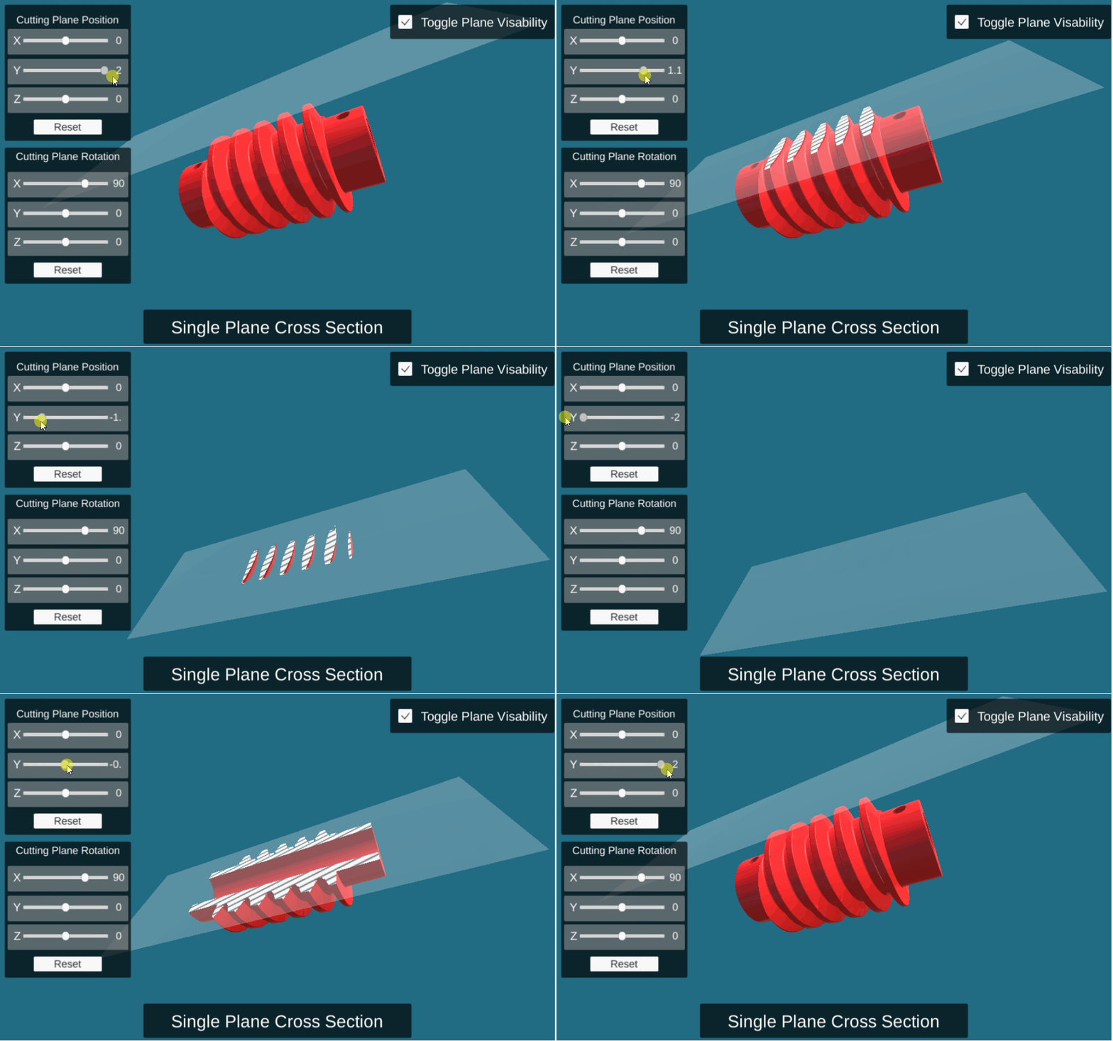
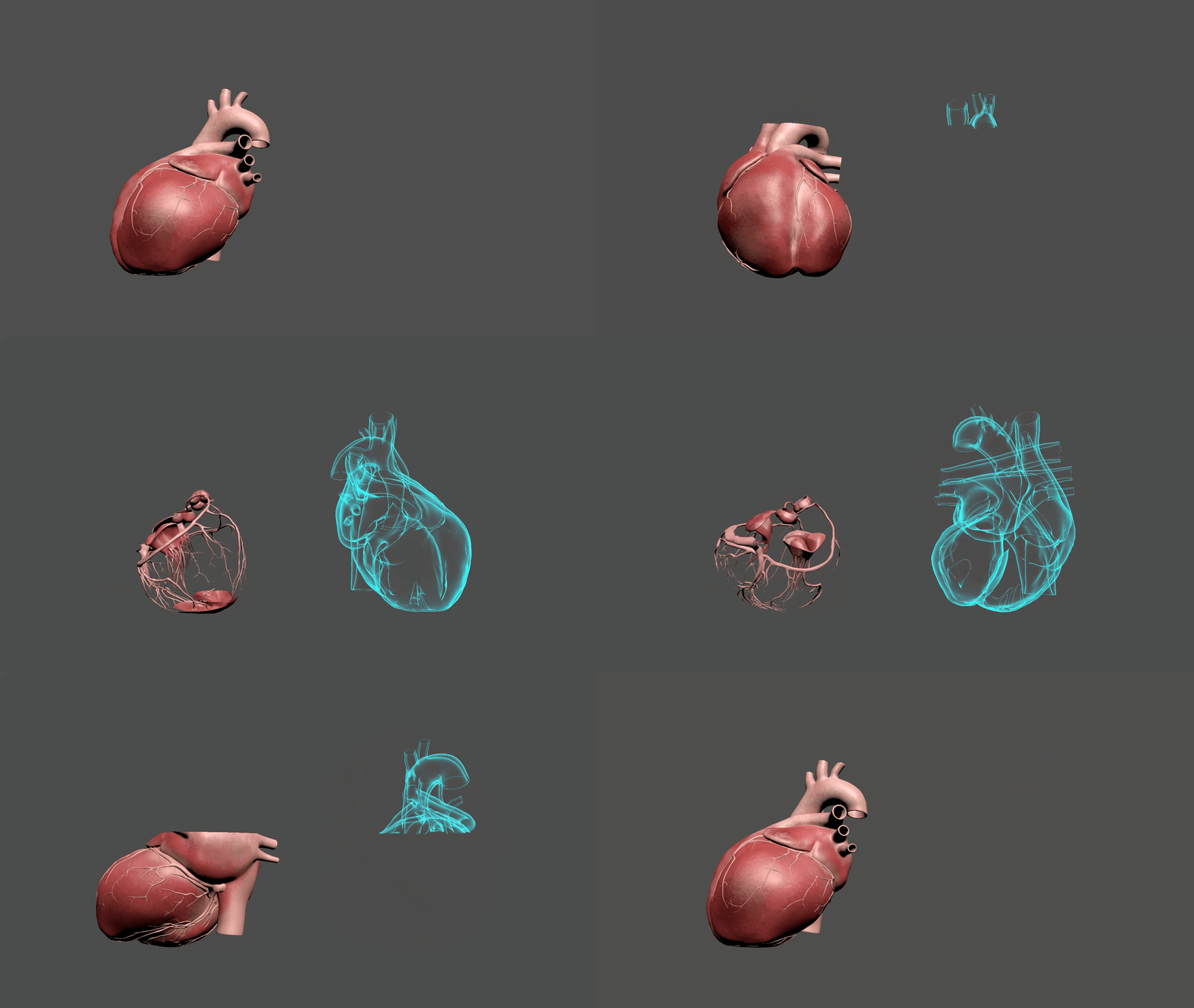
F ew years back, I wrote a simple cross section shader in unity using Surface shader, unfortunately that shader didn’t support different kind of maps (i.e. normal map, height map.. etc.), This week I got a task to visualize human heart with the above effect in which we need to apply color, normal and metallic maps on the heart model.

Updating the old shader to receive different texture maps is not an easy process, So I decided to implement the required effect using Shader graph. In this article I’ll describe how does it work step by step.
The source code for this article is available here:
https://github.com/Dandarawy/UnityCrossSectionShaderGraph
Two Shaders, not one
As the fesrnel (hologram) shader should be in transparent mode, which means it won’t write to depth buffer, it’s not possible to make the desired effect with only one shader, so I decided to write two different shaders and to duplicate the Heart model with the same position and rotation and apply a material with the fesrnel shader on one of them and a material with the texture maps on the other, then we have to control the clipping on both materials with the same parameters, each shader should clip/show the opposite part of the other shader

The Concept
The idea of the cross sectioning is really simple, we should have a clipping plane that is defined by it’s position and normal (plane in 3d can be defined by its normal and any point on the plane), then any pixel above the plane should be discarded and any pixel under the plane should be rendered. The question now is how to determine if the point (pixel) is above the plane or underneath it.
The Math
Determining the point location relative to the plane is quite easy, imagine we have plane with normal n, and point P₀ lies on that plane and we need to determine if point P is above the plane or not, the only thing we need to do is to calculate the dot product between vector n and vector P₀P, if the dot product is positive that means the absolute angle |θ| between n and P₀P is between (0 and 90) and the point P is above the plane, if the dot product is negative that means the absolute angle |θ| between the two vectors is from 90 to 180 and the point is under the plane. So we need to check the value of (P-P₀)·N if it is positive then P is above the plane otherwise P is underneath the plane

The Implementation
As I mentioned we will have two different shaders one for the textured model and one for the Fresnel effect, for detailed step by step guide check the video in the end of the article. Now lets break down both shaders.
Textured Cross Section Shader:

We can divide this shader into two major parts; the textures part and the clipping part:
1. The textures part:

I· Here we need to add three properties for three texture maps; albedo (main texture), normal and metallic
II· Drag and drop each of them to the editor canvas to create property for each of them
III· Connect the texture property node output to the input of a “Sample Texture 2D” node
IV· Connect the output of the Sample Texture 2D node to the respective input of the master node. Just make sure to change the type of the sampling node for the normal map to “Normal” instead of “Default”
Extra Point:
If you need to increase the normal map power (bumpiness) you can add a “Normal Strength” node.
2. The clipping part:

I· First we need to add two vector3 properties for the clipping plane, one for the plane normal and the other for the plane position
II· Drag and drop both properties in the graph canvas
III· Now the only data is missing is the world position of the pixel that we are calculating the clipping for, so we need to add position node and by default Space will be World.
IV· As we want to calculate this value (P-P₀)·N we will add a “Subtract” node to subtract the plane position from world position
V· Then we add “Dot Product” node to multiply the output of the subtraction node and the plane normal
VI· Now we know that if the output value of this calculation is positive then we need to discard this pixel if its negative we keep it, To do that we can connect the output of the “Dot product” node to the AlphaClipThreshold slot of the master node and set the Alpha value to zero
Fresnel Cross Section Shader:
This shader can be divided into two parts as well, the fresnel coloring part and the clipping part, but first we need to change the Surface property of the master node to “Transparent”

- Fresnel Effect

I· Add a color property to control the output color of the shader and float property (Vector1) to control the fresnel power
II· Connect the color property node output to the emission slot of the master node
III· Create “Fresnel Effect” node and connect the output of the fresnel power node to the Power slot of the fresnel node.
IV· Connect the output of the Fresnel node to the Alpha slot of the master node
2. Clipping Part

This part is the same as previous shader but we need two more steps before connecting the output of the dot product to the AlphaClipThreshold slot:
I· We need to flip the clipping effect (to make the clipped part opposite to the previous textured shader), there are many ways to do that, but we can simply use a step node to convert the output of the dot product node from (-1 to 1) range to a binary value (1 or 0), then we connect the output of this node to OneMinus node which is simply (output=1-input), so we will get a binary value (0 or 1)
II· If we connect the output of the OneMinus node to the AlphaClipThreshold slot the shader will work as intended but we will notice some pixels are still rendered in the clipped area (see the video at the end of the article), that’s because the “Alpha” value now is not constant as the previous shader, the Alpha slot is getting it’s value from the Fresnel node, and when the value of the Alpha is 1 and the value of the Threshold is 1 the Alpha test may fail and the pixel will get rendered, what we can do now is to multiply the output of the OneMinus node by two to convert the value of (0 or 1) to (0 or 2) so now we can make sure that the pixels in the clipped part will be always discarded.
Put them all together
Now to achieve the desired effect we need to
I· Duplicate our model in the scene and apply a material with the first shader on first model and apply a material with the second shader on the second one. Make sure the two game objects have the same position and rotation.
II· Control the cross sectioning parameters (Plane position and normal) of two shaders through code, to do that we can create a quad/plane object in the scene and attach a simple script on it that map the plane normal and position to our two materials. The script might look like this:
For full source code of the project check the github repo:
https://github.com/Dandarawy/UnityCrossSectionShaderGraph
For step by step guide check the following video

